Schneider ATV 310 Modbus Tutorial
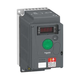
ATV310 Modbus Tutorial Preliminary Notes:
Before you begin, please download the following documents:
1) ATV 310 Modbus Manual (EAV94278)
2) ATV 310 Modbus Address (EAV94279)
Special notes regarding document ATV 310 Modbus Address (EAV94279): All addresses in this document need to be offset by 1. It means address 8501 in the manual shall be treated as 8502 in practical terms.
Powering Up & Connection to PC
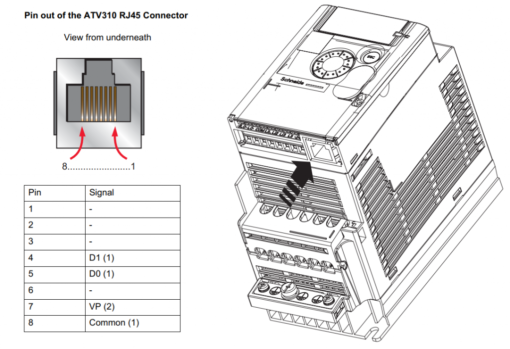
First of all, power up your ATV 310 and connect the RS485 port from the inverter to your PC. This document ATV310 Modbus Tutorial uses a USB/RJ45 connector from Schneider Electric (Part no: TCSMCNAM3M002P) but any other USB/RS485 converters can be used provided that the pin out of the converter matches the diagram below. More information can be found in Page 9 of the ATV 310 Modbus Manual (EAV94278).
Inverter Settings
For the purpose of this demonstration, there are several settings to be changed at the inverter. There are as follows;
701 set to 1 [Modbus Address]
702 set to 19,2 [Default Baud Rate]
703 set to 8E1 [Default 8bit, even parity, 1 stop bit]
401 set to 164 [Frequency Reference set to Modbus]
406 set to 00 [Set Channel config to Separate]
407 set to 10 [Start Command set to Modbus]
By now your inverter should display [- – 0 6]. Fret not, it is normal.
Next, determine the correct port number of your converter by checking under Device Manager, Ports. Depending on your machine, it can be assigned to different port numbers.
Interfacing with the inverter using Modscan
Now fire up Modscan and you should be greeted by the following window;
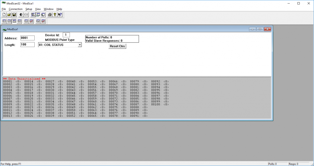
Click Connection and then select Connect.
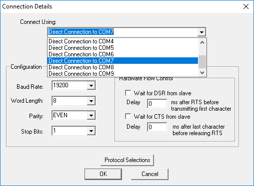
Change the COM to match your converter number and double check on the values of Baud Rate, Word Length, Parity and Stop Bits. In this example, COM7 is used. Click OK and Modscan will start to ping the inverter.
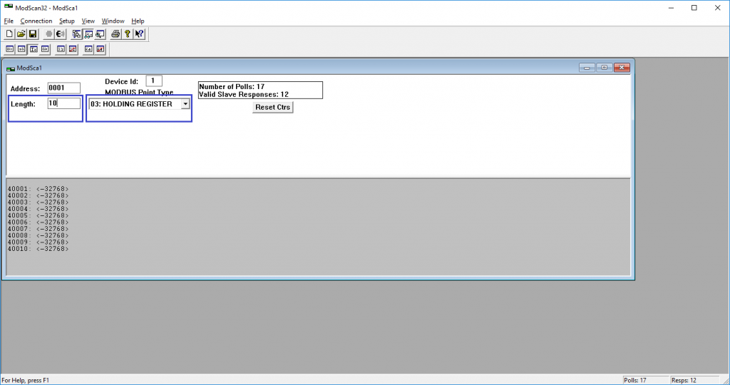
Change the Length to 10 and Point Type to HOLDING REGISTER. The red error should be gone and you should see the number of polls and slave response increase accordingly. Congratulations, you have established the modbus link!
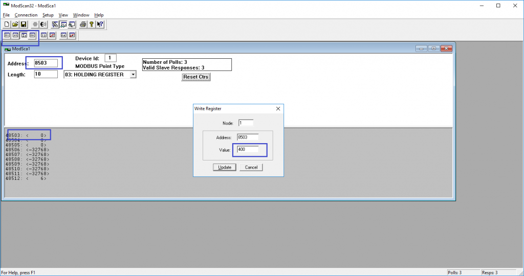
Next, select the Integer mode, key in address 8503 and double click on the grey window area. A Write Register window will pop out, Key in 400 and click Update. The resolution of this number is 0.1hz so the 400 value represents 40.0Hz.
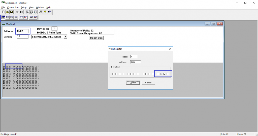
Select Binary mode, key in address 8502 and double click on the grey window area again. Write bit 1 and bit 2 as shown in the screen above. (Remember, this array starts from right side as most significant bit and starts at bit0). You may also choose to input this is a HEX value of 6 which is equivalent.
The display of the inverter should now change to [- – 0 0] in ready state.
To run the inverter, set bit 0 and bit 3 to 1. The inverter will start accelerating towards target frequency and at this stage, if you do not have a motor connected, Fault F015 will appear. Simply change parameter 605 (Output fault monitoring) to 00 to temporary disable this alarm but remember to enable it for protection once testing has ended.
To stop the inverter, set bit 3 to 0.
Further Information
For more information on this ATV310 Modbus Tutorial or what you can do with the inverter especially on parameter address 8502, refer to ATV 310 Modbus Address (EAV94279) in Registers tab. For example, bit 11 can be set to reverse the motor direction. Furthermore, Motor direction can also be reversed by setting a negative number in parameter 8503 such as -400 which will represent 40.0hz in the reverse direction.
For more information, visit ATV 310 product page.

